
Page 19 - MFW Dec 2024
P. 19
chosen that precise moment to fail. Never mind, after almost a year
since my first taxi runs I hadn’t come this far to give up; a complete
rebuild was well advanced at the time of writing and I hoped to have it
back in the air shortly afterwards.
In conclusion
It’s been an absorbing project. While I’ve been able to draw on years of
full-sized building and flying skills, it’s a complex model and there have
been myriads of issues to sort out with the design, fabrication and
printing. I’ve thoroughly enjoyed making the necessary tools,
prototyping and perfecting my ideas and learning new stuff so it’s been
an ideal way to keep my retired brain cells active. That, after all, was a
prime reason for taking up this fascinating hobby in the first place!
CAD Design and 3D Printing
· For 3D CAD software I use OnShape which is free to download and use as long as you're
prepared to allow any other user to access your work. It's fully featured industrial quality
software that's just as powerful as the packages I had at work. Added benefits are that there
are no licences to update, it will run on almost any computer (even your phone!) and it resides
in the cloud so is fully up-to-date every time you open it.
· My printer is an Ender 3 Neo which sits on a shelf in my garage. After using it for a while I
made an enclosure to keep it clean and ambient temperatures more stable as sudden
changes, such as when the garage door opens, can make the difference between a good
print and a failure.
· I use Ultimaker Cura printer slicing software. The slicer converts a CAD model into machine
language for the printer. It's a free download and is immensely powerful with a myriad of
settings to play with as you get to know what you're doing (which I do - sometimes….!).
· I've used PETG filament (similar to drink bottle material) for all the parts for this project. It's
only slightly more difficult to print than the most common PLA material but is stronger, more
flexible and withstands UV light better. ABS may be better still but is reputedly harder to work
with and requires the print nozzle and bed to run at high temperatures. I've upgraded the
printer to suit but I would prefer to add a filter system to the enclosure to trap unfriendly gases
generated in the printing process. PETG has worked well.
· It takes a while to learn how to design parts for printing, how to orientate them on the print
bed and what settings to use. With experience I'm getting better results and saving a lot of
time and filament by minimising overhanging areas, which need temporary towers to build
upon. I'm also putting more thought into the effects of material shrinkage, which can be an
issue when printing some parts. Specs at time of writing:
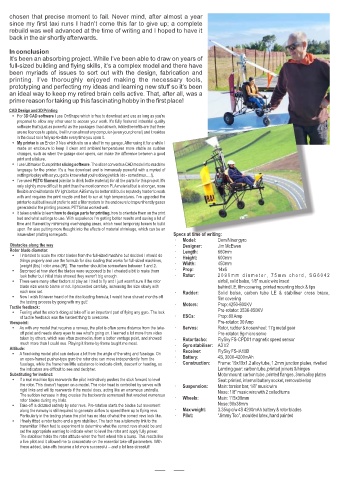
· Model: DomiNiner gyro
Obstacles along the way · Designer: Jim McEwen
Rotor blade diameter: · Length: 660mm
· I intended to scale the rotor blades from the full-sized machine but decided I should do · Height: 600mm
things properly and use the formula for disc loading that works for full-sized machines,
[weight (lbs) / rotor area (ft²)]. The number should be somewhere between 1 and 2. · Width: 450mm
· Surprised at how short the blades were supposed to be I cheated a bit to make them · Prop: 14x6
look better but initial trials showed they weren't big enough. · Rotor: 2 0 9 0 m m d i a m e t e r, 7 5 m m c h o r d , S G 6 0 4 2
· There were many other factors at play as I tried to fly and I just wasn't sure if the rotor airfoil, solid balsa, 1/8” music wire insert
blade size was to blame or not. I proceeded carefully, increasing the size slowly with behind LE, film covering, printed mounting block & tips
each new set. · Rudder: Solid balsa, carbon tube LE & stabiliser cross brace,
· Now I wish I'd never heard of the disc loading formula; I would have shaved months off film covering
the testing process by going with my gut!
Tactile feedback: · Motors: Prop: 4250-800KV
· Feeling what the rotor's doing at take-off is an important part of flying any gyro. The lack Pre-rotator: 3536-850KV
of tactile feedback was the hardest thing to overcome. · ESCs: Prop: 80 Amp
Viewpoint: Pre-rotator: 30 Amp
· As with any model that requires a runway, the pilot is often some distance from the take- · Servos: Rotor, rudder & nosewheel: 17g metal gear
off point and needs sharp eyes to see what's going on. I learned a lot more from video Pre-rotator: 9g micro servo
taken by others, which was often zoomed in, from a better vantage point, and showed · Rotor tacho: FlySky FS-CPD01 magnetic speed sensor
much more than I could see. Playing it frame-by-frame taught me most. · Gyro stabiliser: A3 V2
Attitude:
· A fixed-wing model pilot can deduce a lot from the angle of the wing and fuselage. On · Receiver: FlySky FS-iA10B
an open-framed pusher-type gyro the rotor disc can move independently from the · Battery: 4S, 3000-4200mAh
fuselage, while the frame has little substance to indicate climb, descent or heading, so · Construction: Frame: 19x19x1.2 alloy tube, 1.2mm junction plates, rivetted
the indicators are difficult to see and decipher. Landing gear: carbon tube, printed joiners & hinges
Substituting for instinct: Motor mount: carbon tube, printed flanges, 3mm alloy plates
· If a real machine tips rearwards the pilot instinctively pushes the stick forward to level Seat: printed, internal battery socket, removable top
the rotor. This doesn't happen on a model. The rotor head is controlled by servos with · Suspension: Main: torsion bar, 1/8” music wire
rigid links and will tip rearwards if the model does, acting like an enormous umbrella. Nose: 1/8” music wire with 2 coiled turns
The sudden increase in drag creates the backwards somersault that wrecked numerous
rotor blades during my trials. · Wheels: Main: 115x38mm
· Take-off is dictated entirely by rotor revs. Pre-rotation starts the blades but movement Nose: 90x38mm
along the runway is still required to generate airflow to speed them up to flying revs. · Max weight: 3.35kg c/w 4S 4200mAh battery & rotor blades
Particularly in the testing phase the pilot has no idea of what the correct revs look like. · Pilot: “Jimmy Too”, moulded latex, hand painted
· I finally fitted a rotor tacho and a gyro stabiliser. The tach has a telemetry link to the
transmitter. I then had to experiment to determine what the correct revs should be and
set the appropriate warning to indicate when to level the rotor and apply fully power.
The stabiliser holds the rotor attitude when the front wheel hits a bump. This reacts like
a live pilot and it allowed me to concentrate on the essential take-off parameters. With
these added, take-offs became a lot more successful – and a lot less stressful!
14