
Page 15 - MFW Dec 2024
P. 15
gear but replaced the original air-shock units with simple This time I cut a slot in the leading edge with a bench saw
torsion bar springs. For the front wheel I wound a spring and glued in a flat aluminium extrusion to achieve the
similar the donor Bensen, but lighter. I used the original correct c-of-g position. I printed new sanding blocks and
wheels which were slightly large but gave the model a used only one guide rail. I screwed both blades (still both
more modern, robust, bush-plane look. They and the very part of the same piece of balsa) to the table and roughed
effective suspension would hopefully prove ideal for the them out with a plane. It took 30 minutes of sanding to get
Club’s grass strip. the tops accurately shaped. I printed supports that
matched the shape of the top, turned the blades over and
Power screwed them onto the supports so they were in exactly
All my models are electric-powered and the gyro was
always going to be the same. I chose a 4250 800kV motor
because I happened to have one spare and a 15x4” prop
because I had some I’d ordered clockwise by mistake
(one of the joys of shopping online…!). Going electric
meant finding somewhere for the battery. Fortunately
most gyros use the pilot’s seat as a fuel tank, the
Dominator being no exception, so I managed to keep the
seat looking reasonably “scale” with room to
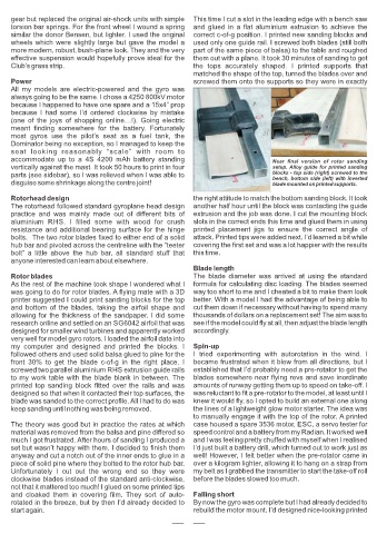
accommodate up to a 4S 4200 mAh battery standing Near final version of rotor sanding
vertically against the mast. It took 50 hours to print in four setup. Alloy guide for printed sanding
parts (see sidebar), so I was relieved when I was able to blocks - top side (right) screwed to the
bench, bottom side (left) with inverted
disguise some shrinkage along the centre joint! blade mounted on printed supports.
Rotorhead design the right attitude to match the bottom sanding block. It took
The rotorhead followed standard gyroplane head design another half hour until the block was contacting the guide
practice and was mainly made out of different bits of extrusion and the job was done. I cut the mounting block
aluminium RHS. I filled some with wood for crush slots in the correct ends this time and glued them in using
resistance and additional bearing surface for the hinge printed placement jigs to ensure the correct angle of
bolts. The two rotor blades fixed to either end of a solid attack. Printed tips were added next. I’d learned a bit while
hub bar and pivoted across the centreline with the “teeter covering the first set and was a lot happier with the results
bolt” a little above the hub bar, all standard stuff that this time.
anyone interested can learn about elsewhere.
Blade length
Rotor blades The blade diameter was arrived at using the standard
As the rest of the machine took shape I wondered what I formula for calculating disc loading. The blades seemed
was going to do for rotor blades. A flying mate with a 3D way too short to me and I cheated a bit to make them look
printer suggested I could print sanding blocks for the top better. With a model I had the advantage of being able to
and bottom of the blades, taking the airfoil shape and cut them down if necessary without having to spend many
allowing for the thickness of the sandpaper. I did some thousands of dollars on a replacement set! The aim was to
research online and settled on an SG6042 airfoil that was see if the model could fly at all, then adjust the blade length
designed for smaller wind turbines and apparently worked accordingly.
very well for model gyro rotors. I loaded the airfoil data into
my computer and designed and printed the blocks. I Spin-up
followed others and used solid balsa glued to pine for the I tried experimenting with autorotation in the wind. I
front 30% to get the blade c-of-g in the right place. I became frustrated when it blew from all directions, but I
screwed two parallel aluminium RHS extrusion guide rails established that I’d probably need a pre-rotator to get the
to my work table with the blade blank in between. The blades somewhere near flying revs and save inordinate
printed top sanding block fitted over the rails and was amounts of runway getting them up to speed on take-off. I
designed so that when it contacted their top surfaces, the was reluctant to fit a pre-rotator to the model, at least until I
blade was sanded to the correct profile. All I had to do was knew it would fly, so I opted to build an external one along
keep sanding until nothing was being removed. the lines of a lightweight glow motor starter. The idea was
to manually engage it with the top of the rotor. A printed
The theory was good but in practice the rates at which case housed a spare 3536 motor, ESC, a servo tester for
material was removed from the balsa and pine differed so speed control and a battery from my Radian. It worked well
much I got frustrated. After hours of sanding I produced a and I was feeling pretty chuffed with myself when I realised
set but wasn’t happy with them. I decided to finish them I’d just built a battery drill, which turned out to work just as
anyway and cut a notch out of the inner ends to glue in a well! However, I felt better when the pre-rotator came in
piece of solid pine where they bolted to the rotor hub bar. over a kilogram lighter, allowing it to hang on a strap from
Unfortunately I cut out the wrong end so they were my belt as I grabbed the transmitter to start the take-off roll
clockwise blades instead of the standard anti-clockwise, before the blades slowed too much.
not that it mattered too much! I glued on some printed tips
and cloaked them in covering film. They sort of auto- Falling short
rotated in the breeze, but by then I’d already decided to By now the gyro was complete but I had already decided to
start again. rebuild the motor mount. I’d designed nice-looking printed
10